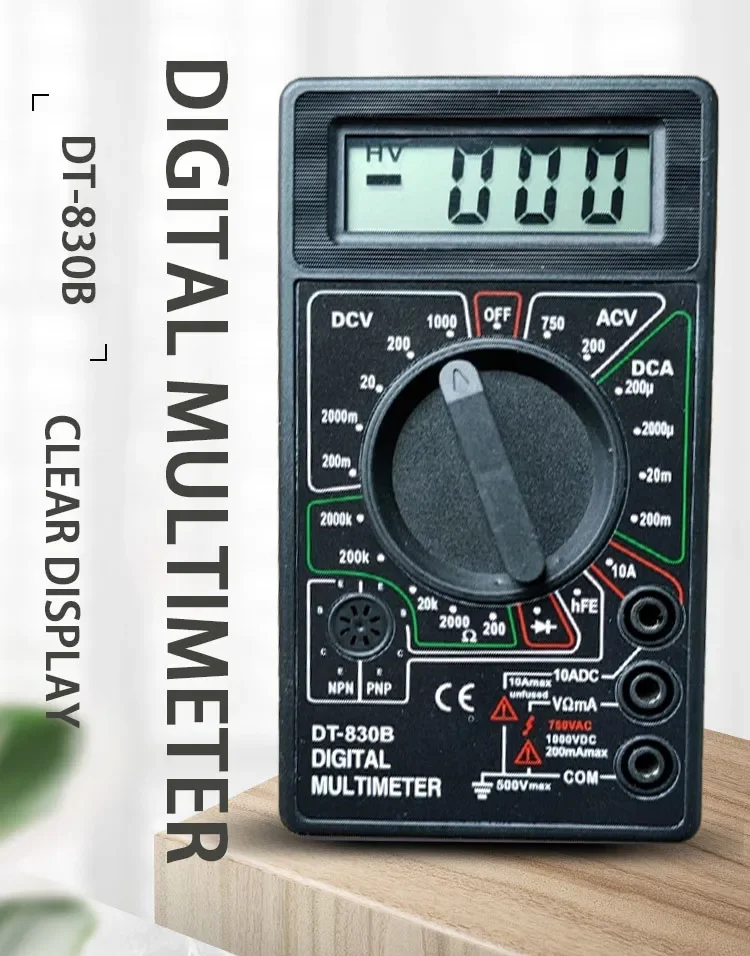
Digital Multimeter
- High Precision Multimeter: The DT830B LCD Digital Multimeter is a high precision tool, ensuring accurate readings for AC/DC Voltmeter, Ammeter, and Ohm Meter functions.
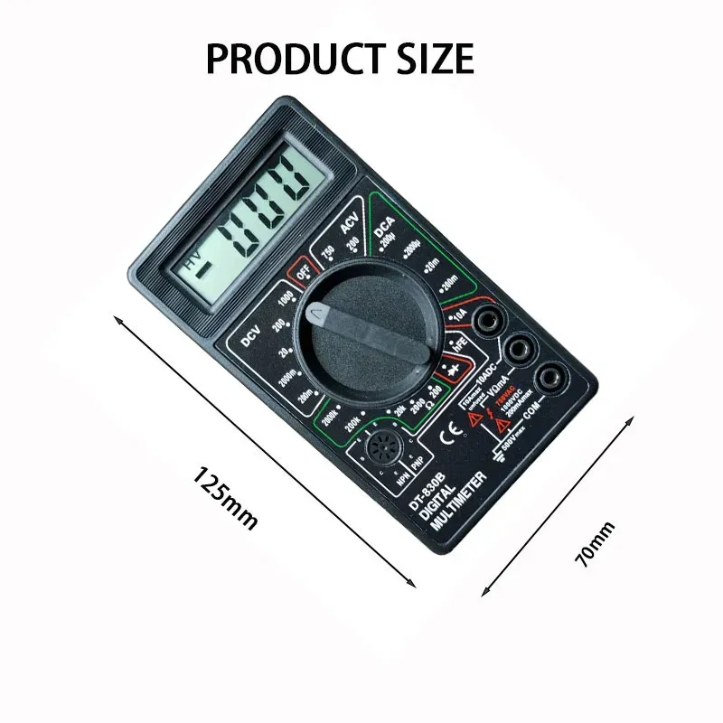
- Compact and Portable: Its compact design makes it easy to carry around, perfect for on-the-go professionals who need reliable testing equipment at all times.
- Versatile Tool: This multimeter is a versatile tool, combining Ammeter, AC/DC Voltmeter, and Ohm Meter functions in one device, saving you the cost of purchasing multiple meters.
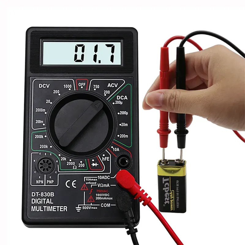
- Includes Probe Combination: The product comes with a probe combination, providing you with everything you need for efficient and accurate testing.
- Brand Trust: Coming from a trusted brand, this multimeter guarantees durability and reliable performance, making it a great investment for your toolkit.
- Ideal for DIY Supplies: With its electrical DIY supplies, this multimeter is an ideal choice for DIY enthusiasts and professionals alike.
Product technical features:
- DC voltage: 200-2000-20-200-500V ± 0.5%
- AC voltage: 200-500V ± 1.0%
- DC current: 200u-2000u-20m-200m-5A ± 1.8%
- Resistance: 200-2000-20K-200K-2000K ± 1.0% ± 1.0% .
- General features of the product:
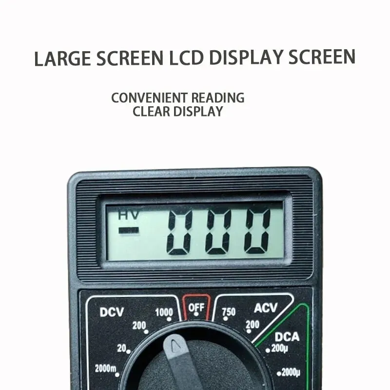
- LCD display size
- Low voltage symbol display: Yes
- Overload protection: yes
- Diode detection: yes, showing approximate voltage drop
- Detection of triode: yes
- Power supply: 6F22 9V battery(Without battery)
- Product size: 125x70x25mm
- Standard configuration: Bare meter, color box, pen, manual, certificate of conformity (warranty card)
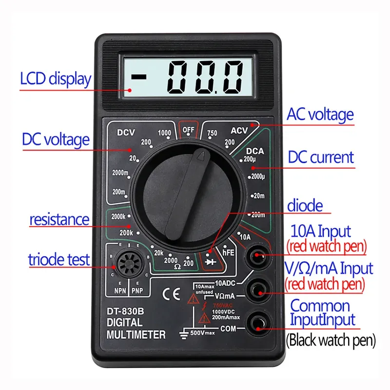
Panel and operating instructions:
1. monitor
Three and a half digit LCD display
2. switch
Press it to turn on the power, and turn it off when not in use.
3. Capacitance measurement socket
This watch has no capacitance test function.
4. Function range switch
Choose from different measurement functions and ranges.
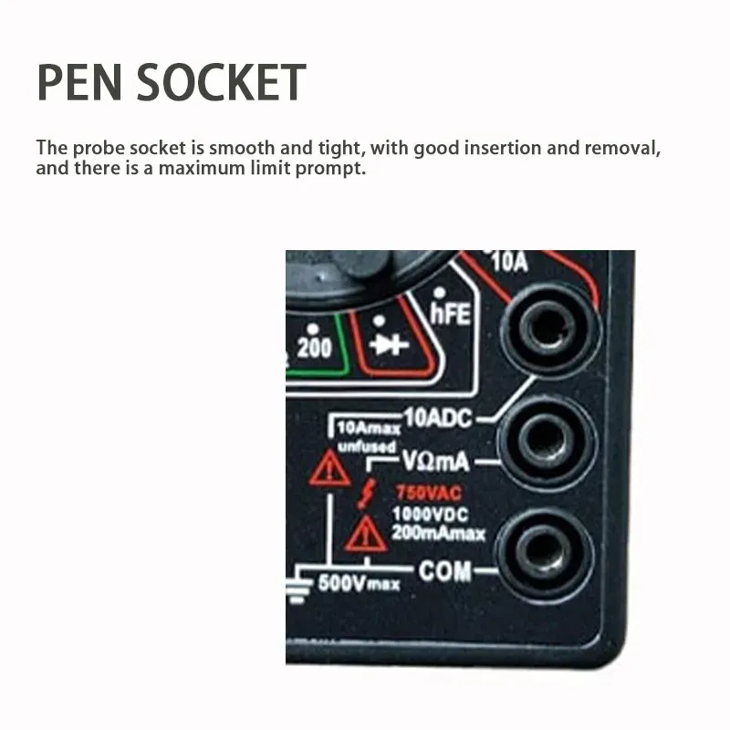
5. 10A current jack (cannot measure current greater than 10A)
When measuring AC and DC currents greater than 200mA and less than 10A, the red test lead should be inserted into this 10A current jack.
6. current jack
When measuring AC and DC currents less than 200mA, the red test lead should be inserted into this current jack.
7. V/Ω jack
When measuring AC and DC voltage, resistance, diode conduction voltage and short circuit detection, the red test lead should be inserted into this V/Ω jack.
8. The black test lead of the grounding common end "COM" jack is always inserted into this grounding jack.
9. β value test socket
Insert the collector, base and emitter of the triode under test into the "C", "B", and "E" jacks respectively, and pay attention to distinguish whether the triode is NPN or PNP.
Instructions:
1. Prepare
Press the power switch, observe whether the LCD display is normal, and whether there is a battery shortage sign, if so, replace the battery first.
2. Use
(1) Measurement of DC current
Select the appropriate current measurement range and the insertion hole of the red test lead according to the size of the measurement current. When measuring DC, the red test lead touches the end with high voltage, the black test lead contacts the end with low voltage, and the forward current flows from the red test lead. Flow into the multimeter, and then flow out from the black test lead. When the magnitude of the current to be measured is not clear, first use the largest range to measure, and then gradually reduce the range to measure accurately.
(2) Measurement of AC and DC voltage
Insert the red test lead into the "V/Ω" jack, select the appropriate voltage measurement range according to the voltage, the black test lead touches the "ground" end of the circuit, and the red test lead touches the point to be measured in the circuit. In particular, it should be noted that the frequency of AC voltage measured by the digital multimeter is very low (45 ~ 500Hz), and the voltage amplitude of the medium and high frequency signal should be measured by an AC millivolt meter.
(3) Measurement of resistance
Insert the red test lead into the "V/Ω" jack, select the appropriate resistance measurement range according to the size of the resistance, touch the red and black test leads to both ends of the resistance, and observe the reading. In particular, when measuring in-circuit resistance (resistance on the circuit board), the power supply of the circuit should be turned off first, so as not to cause reading jitter. It is forbidden to use resistance gear to measure current or voltage (especially AC 220V voltage), otherwise it is easy to damage the multimeter. In addition, the resistance file can also be used to qualitatively judge whether the capacitor is good or bad. First short circuit the two poles of the capacitor (use a test lead to touch both poles at the same time to discharge the capacitor), then touch the two test leads of the multimeter to the two poles of the capacitor respectively, and observe the displayed resistance reading. If the resistance reading displayed at the beginning is very small (equivalent to a short circuit), then the capacitor starts to charge, the displayed resistance reading gradually increases, and finally the displayed resistance reading becomes "1" (equivalent to an open circuit), then the capacitor is OK If the above steps are followed and the displayed resistance reading remains unchanged, then the capacitor is damaged (open circuit or short circuit). Special attention should be paid to the selection of the appropriate resistance range according to the size of the capacitance when measuring, for example, 200k range for 47μF, 2M range for 4.7μF, etc.
(4) Diode conduction Volting detection
In this gear, the red test lead is connected to the positive power supply inside the multimeter, and the black test lead is connected to the negative power supply inside the multimeter. The connection between the two test leads and the diode is shown in Figure 1. If it is measured according to the connection method in Figure 1 (a), the diode under test is conducting forward, and the multimeter displays the forward conducting voltage of the diode in mV. Usually, the forward conduction voltage of a good silicon diode should be 500mV to 800mV, and the forward conduction voltage of a good germanium diode should be 200mV to 300mV. If "000" is displayed, it means that the diode is short-circuited, and if "1" is displayed, it means that the diode is not forward. If it is measured according to the connection method in Figure 1 (b), it should display "1", indicating that the diode is reversely cut off. If it displays "000" or other values, it indicates that the diode has reversely broken down. This file can also be used to judge the quality of the triode and identify the pins. When measuring, first connect one test lead to a designated pin, and connect the other test lead to the other two pins successively. Change two test leads and test again. If they are not turned on or both are turned on twice, it can be confirmed that the triode is good, and it can be confirmed that the identified pin is the base of the triode. If the red test leads are connected to the base and the black test leads are respectively connected to the other two poles, it means that the triode is NPN type, otherwise, it is PNP type. Finally, compare the forward conduction voltage of the two PN junctions. The larger reading is the be junction, and the smaller reading is the bc junction, so the collector and emitter are identified.
(5) Transistor value β test
First of all, it is necessary to determine whether the triode to be tested is NPN type or PNP type, then insert its pins into the corresponding type of test socket correctly, and turn the function range switch to the β position, that is, the β value can be read directly from the display screen. "000", it means that the triode is broken.
No reviews found